(1).png?x-oss-process=image/resize,w_200/quality,q_100)


Product description
-
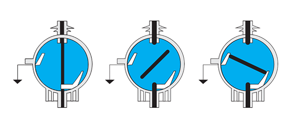
BRFLN36 series indoor high-voltage SF6 load break switch, It is widely used in 11~24kV electric power distribution system , adopted with SF6 gas as an arc-extinguishing and insulation medium, including the three contactors for switching-on and switching-off and to-ground, and is characteristic in its small volume, its convenient installation and operation and its the great adaptability with surroundings.
-
Indoor high-voltage SF6 load break switch and SF6 load break switch plus fuse combination can function to protect and control the electric equipments for power supply and transformer substations especially being suitable for ring net cabinet, cable branch cabinet and distribution switching substation. indoor high-voltage SF6 load switch and SF6 load break switch plus fuse combination are complied with the standards of IEC60265-1-1998, IEC60420 etc.